The workshop manual makes this seem an easy task;
The book states the job is done by:
Removing the gear knob and lever gaiter tray,
Remove radio,
Remove heater control knobs'
Pull out the two face level vents, and, reaching through the vent holes undo the two butterfly nuts that hold the aluminium face plate on.
Pull the fascia plate forwards and down to disengage from the dash.
Sounds simple enough- but it isn't straightforward and there are a few pitfalls- my experience and suggestions follow!
The gear lever and gaiter are straightforward.

Unscrew the gear knob

Lift up the rear of the gear lever tray and slip it off over the gear lever.
Removing the Radio
Despite the instruction to remove the radio- this can't be done until the dash is off, so I first just disconnected the the knobs

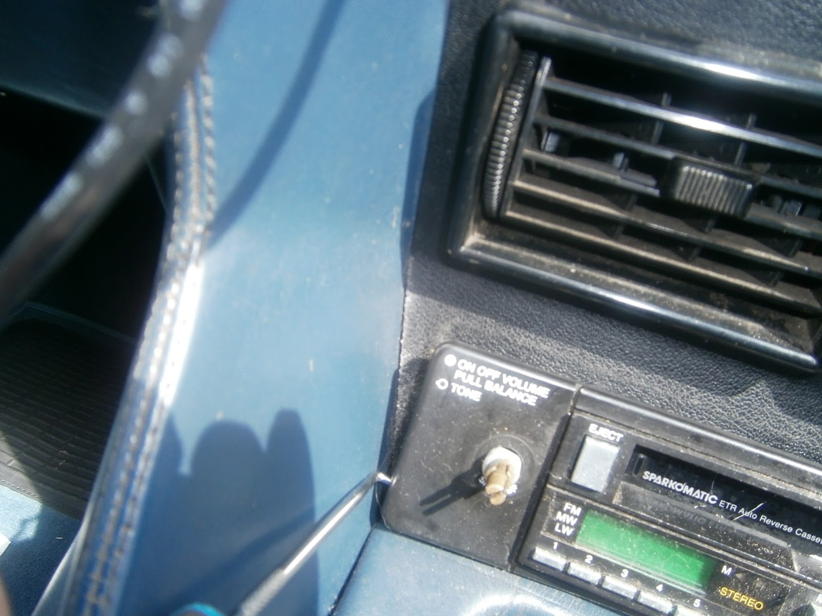 |
| Pulling the fascia frame |


There's little room for a spanner so I removed them with a wall-drive through the socket.

The radio is then loose but can't be removed until the main fascia panel is off!

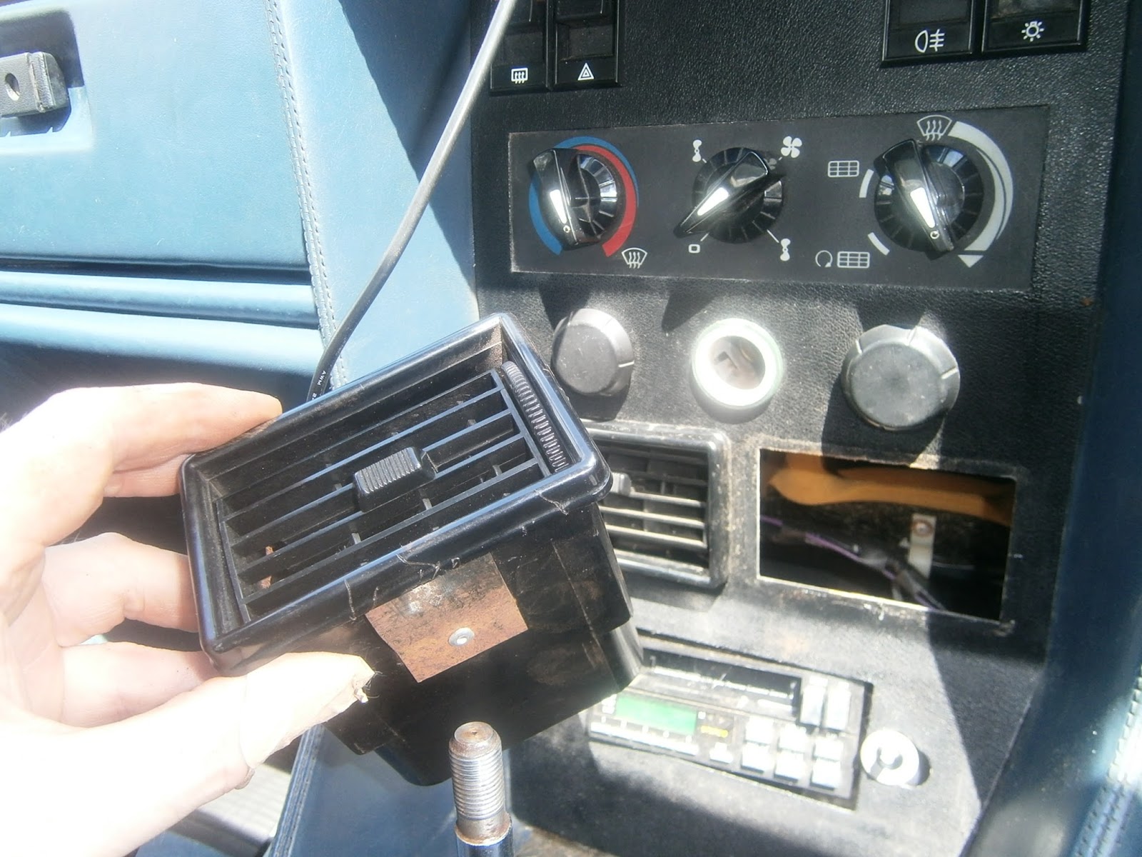
Face Level Vents
The book says that these should pull out- they don't. This is a difficult and time-consuming job that will take a couple of hours! It will also shred your hands. The vents will not pull out because they are secured from behind by two spring clips. The only diagram I could find suggested that these are at each side of the vent- they are not. In my car at least they are fitted to the top and bottom of each vent. They can just be reached from each side if you remove the inboard knee panels and reach up behind the dash. If you have very long and strong fingers you can probably squeeze the clips together and pull/push the vent forwards- not many of us are built like this! The clips are tight because they are hard up against the material of the console from behind- they tend to dig in to the softer plastic and then can't be pushed down.
I found it was best to start with the top clip- press it down using a lever if necessary, and tip the vent forwards so that the top slips out. If you then try to release the bottom, the top will clip back in, so I laid an aerosol can spray extn tube along the top of the vent to prevent it from popping back into place.
 |
| Aerosol extn tube (white) in position across the top of the vent |

 |
| Vent released, note wide clips on top and bottom |

Vent removed. The hole does provide extra access but I found I had to remove the other kick plate anyway.

 |
| Scratches on vent surround from abortive attempts at levering. |

Removing the Fascia panel
The panel is held on by two butterfly nuts, one each side of the fascia, and accessible through the FLV holes- tricky to photograph but they are in there! |
| One butterfly nut just visible towards bottom left side |
 |
| Butterfly nuts removed |
 |
| I removed one of the panel dimmer knobs- this was VERY tight and stuck on with black gooey stuff. I gave up removing the second! |
 |
| LHS directional control knob. Note spring-loaded button on knob stem... and damage :-{ to backplate. |
 |
| Hole in knob into which the spring loaded stalk button will clip |
 |
| Top lip on dash fascia panel. Note switches come forward with the panel, as do the two panel light control knobs. |


Lighting, HRW hazard warning and rear foglight switches
The four top switches are clipped into the fascia panel and come forward with it. However they have to come off in order to remove the panel. They have a plastic latch on top and two lugs beneath. In my case the lighting switch lacked the two bottom lugs. The switches are made in two black plastic parts and are surrounded by a white fibre-optic collar for illumination. They join the loom via white multi-plugs at the rear. There is actually only one multi plug per switch- it just looks like two. |
| Switches still fitted in fascia plate. Note white multi-plugs to rear and fibre-optic collar surround. |
 |
| Retaining latches at the top are visible. |


... before removing them.

I did the same to the panel light connections on the right- these join the two centre contacts.

 |
| Two connectors removed form RHS panel light dimming control. |
Cigar Lighter
The cigar lighter was badly corroded both inside and out. There were two connections to the back and a single wire connection to the light ring. |
| Connections to rear of cigar lighter- two to the lighter itself and one for the illuminated ring. |


 |
| Parts removed. |

 |
| Old light ring- note metal peg projecting from the bulb holder that earths the bulb to the lighter body. |
The new light has two leads

The red power lead can be connected to the original power lead for the light, and the earth is connected to the lighter body using a piggy-back spade so that the original earth lead can still be connected.
 |
| Piggy back spade connector on black earth lead to preserve contact point for lighter earth. |
I connected everything temporarily to check function and everything was in order.- care the lighter gets hot in use!

Repairing the lighting switch

The pins at the rear of the switch looked fine

But looking inside the contacts appeared dirty and discoloured.
 |
| Base of switch- poor contacts inside. Note the two spring-loaded plunger resting on the centres of each rocking contact. |
 |
| top of switch- dirty copper inside. |
The switch is in two sections held together by a pip-and-strap on each side. These just lever away from the body and allows the contact block to be withdrawn.

The switch has two rocking contacts inside, each held down by a spring-loaded plunger- both were very dirty.

The rocking contacts should make and break contact with these buttons in the rear section of the switch. These were also very dirty
 |
| Sorry about the poor focus but the muck on the contact studs is clearly visible. |
The switch flick button pulls off the rear section with the contacts and all could be removed for cleaning
 |
| Contacts after one has been removed and cleaned... does it show? |
 |
| Contact studs also cleaned |
I could then reassemble the switch and reconnect it to the loom. I temporarily connected the battery so I could check that it worked and it appeared to do so. There were however no panel lights because both panel dimmer rheostats were disconnected.
Renovation of fascia panel.
The light box provides illumination behind the heater control knobs. Its fronted by a translucent panel stuck to the fascia panel and edged with foam- presumably to stop the light from straying.


I had a bit of an accident with this and the plate was damaged. It seems virtually impossible to replace- it isn't even shown in the parts list and so has no part number, so I will have to carry on with whatever I have left.
The light box back itself remains in the dash. This has a reflective backing and contains 3 2W instrument bulbs BA7S. One is far left, one centre (enters from an angle above) and the final one is at the extreme right. In my case the centre bulb was broken and the right hand one inoperative. I will replace all with new ones as I don't want to be doing this again soon!

Face level vents
The edges of the vents were scratched in my attempts at removal. I filled the scratches with stopping and let it set
Before rubbing it down with 380 grit paper until only the scratches still held filler.

I could then just dust over the frame using black plastic spray paint.


All painted items were left for 24 hrs to dry.
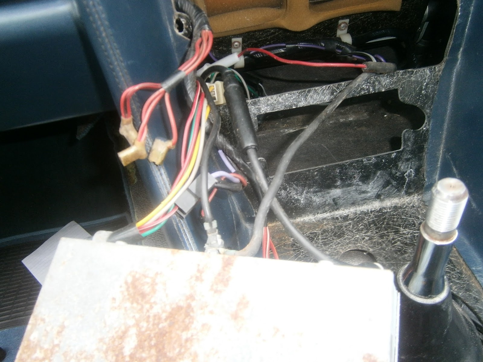
Wiring the radio
It was obvious that there was a lot of debris behind the dash- years of sedimented sweet wrappers, dust, and grit. I vacuumed all out carefully revealing a large rusty metal plate (unknown function but I suspect important) and- surprisingly a spare heater control knob. This one had the spring contact hole and I suspect it was once the centre knob in my panel but was dropped behind the dash at some point. Rather than retrieve it, it was simply replaced with a non-standard knob. I will see about reinstating it when I rebuild!

The radio could be lifted out

... to reveal the expected mess of wiring... and a very rusty radio case.

 |
| Note 4-pin multi-plug on existing radio. |
NOTE ADDED LATER:
This setup is WRONG! It will result in a large battery drain because the clock isnt supposed to be displayed unless the ignition is on. The red/white wire is a permanent live but the red should be a switched live. I was forced to revisit this when I kept going through batteries. This will be covered in a later blog so please see here.


Reassembling the Fascia Panel
I refitted the light box panel by slipping it over the two retaining studs and tightening the 8mm nuts- but only loosely.

The translucent panel was originally edged in foam strip, I used foam sticky tape to edge it as I refitted it.

The end result at this stage is a reasonably firm but movable panel as you will need it to move to align the heater control knobs later on. I think in an ideal world you would do a couple of test fits and tighten the nuts fully when its right- life is too short so I compromised- you don't have to!
 |
| Panel refitted- firm but has some slippage movement. Sadly note the damage I did to the thing by putting it down on some unset filler!- Can't remove that but as the part is obsolete I'm stuck with it. |
Once the panel was back together, refitting is, as they say, the reverse of disassembly.- Except its not exactly that, because I found the new radio had some extra parts that the old one was lacking. For a start there were these nice little rubber dish washers that cover the nuts below the tone and frequency selection tab controls.


This also meant that I needed to experiment with the various fittings to get the right method of installation- and I still don't think I have it right. What I opted for in the end was this...
Fit the metal tabs onto the knob stalks and above the first ring nut. Insert the radio through the upper opening and drop it down so that the knob stalks now protrude through their holes.
 |
| inserting the radio |
 |
| further... |
 |
| lower it and.. |
 |
| Pull forward to allow the knob stalks to project forward. Note the plates fitted behind the GRP |
Holding the radio firmly against the dash from the inside check that the front piece projects through equally on both sides. If it doesn't, adjust the nuts behind the plates to equalise fore/aft projection both sides. The rest of the fitting has to wait until after the fascia plate is fitted but I recommend checking for function at this point - I didn't because its a faff to have to keep connecting and reconnecting the battery- I wish I had though because in my case function had ceased and I had to strip everything out again! This also goes for the switched by the way.
At this stage replace any bulbs in the light box that need changing- I fitted three new ones. You can then start to fit and wire up the switches etc on the fascia panel. I started with the cigar lighter- straight forward when you follow the instructions! Insert the light ring first (bulb holder at top). Insert the lighter body (large slots horizontal) and then twist it clockwise to lock into the light ring.
 |
| Inserting light ring |
 |
| Body inserted and locked, wiring completed |
 |
| insert element |

Fitted the fibreoptic rings and multiplug connectors. However- do not click the switches fully home because that will leeave insufficient clearance to fit the top of the fascia plate under the dash lip. Leave them loose at this stage- I had to unclip mine later!


With the four control buttons loosened and pulled forwards, offer up the panel to the dash. You will need to keep the bottom forward against the gear gaiter and slip the retaining lip under the dash at the top. You can then ease the bottom of the fascia panel backwards making sure that the radio controls emerge through their respective holes as you do so. The heater control knobs also need to project through the holes in the translucent light box frontspiece but will probably not be central at this stage.
 |
| Dont forget to check and change any of the tiny capless bulbs that are used as indicators inside the hrw and foglight control buttons. |


 |
| Adjusting fore/aft projection, washers over knob stalks |
 |
| Add frontspiece and fix with ring nuts covered with rubber dished washers |
 |
| Finally refit all control knobs |
 |
| Dash fascia reinstalled. |
Addendum...
Of course refitting the gear lever tray and trim panels is straightforward- except that I found a split in the gear gaiter... |
| Oops! I found the gear lever gaiter was split... another job for later! |
 |
| This is the inside of the popper fastening that holds the knee panel to the centre tunnel below the dash. Sadly mine pulled apart and although I'd like to replace it I need to find an original fitting. Its an important fastener and needs to be secure. In the pic you can see that I have pop rivetted the head back as a temporary fix. |
Fibre-optic sender and radio fix
I think I mentioned that I will need to tackle this job again to fix the radio. I eventually got around to it and was pleased to find that this time the stripping out of the centre fascia was pretty quick, taking only about 20 mins- largely because the face vents were much easier to remove.
I needed to address the non-working radio- which turned out to simply be an incorrect fuse- it needs two 5a; and also to sort the fibre-optics which, despite my earlier confidence, appeared not to work when tested!
The fibre-optic sender was visible through the top cutout in the dash as an octopus like structure screwed onto the scuttle or bulkhead. It resembles a mini distributor- a silver base and a black plastic cap. This is in fact exactly what it is as its simply an enclosed bulb holder fitted with a cap that contains lenses to focus the light onto several openings into which are inserted fibre-optic cables. In some forms the lenses are also coloured so a different colour can be fed along each cable.
 |
| Fibre-optic source screwed to bulkhead. Note silver half section to left and black cap with optic cables emerging on the right. |
There are lots of pictures of this unit on-line, but nowhere did I find any description of how to take it apart and check the bulb. In fact the bulb holder is a simple push fit in the silver end of the unit. I had to remove the whole thing to work this out as there isn't enough access to pull it with any force until it can be pulled forwards.
 |
| Fibre-optic generator unscrewed and rotated (right) to show the end into which the bulb holder (left) is a push fit. |
Pulling the bulb holder forward to examine it showed that it was in poor condition. The bulb and cap had separated (although this might have happened during the dismantling).
 |
| using a screwdriver to lift the bulb-holder for photography- note the glass bulb has detached. |
The bulb itself was cloudy, I suspect this was intentional, but it has to be admitted that an enclosed unit like this, the usual 6W bulb must get very hot! I decided to swap the bulb for an LED to keep the heat down. Its a BA9 fitting.
 |
| LED fitted into bulb holder- tested for illumination. |
Reassembly was for once, the reverse of dismantling! I have to say that I can still not see much sign of illumination in the daytime- the same goes for the instruments- all of whose bulbs have now been swapped for LEDs. I hope to get a better and more visible display if I ever drive at night.
Hi, I am currently using this blog to plan my own running restoration. Never come across another excel without the digital clock just like mine, is it an A registration thing? Do you have a list of the LED bulbs used on all the instruments and switches. Thanks for posting this blog it really is helpful. Cheers, John
ReplyDeleteHi John, I put a list of the bulbs I used in my reply to your previous comment (final preparations). I think the lack of a clock was a bit of a cop out they got away with because the selected radio had one. I'm not impressed as it means the clock isn't visible unless the sign is on or unless you wire it wrongly ... as I have! See a later blog currently in prep). I'm guessing this didn't really appeal to a refined clientele and got sorted with a proper clock in short order. Mine is an 84 (B) so I guess it was sorted soon after that... Maybe when the fog lights were added as that's another cheeseparing omission.
ReplyDeleteTell me more about your project.
Mike
Hi Mike, mine is an 84 A registered car. Half silver half red, not original obviously but will do until I get around to a repaint (last job on the list). Red interior part leather only 2 owners from new. It has suffered from the usual neglect and bodges but I intend to put these right as time and money allow. Thanks for the reply. John.
ReplyDelete